Sunday, November 7, 2010

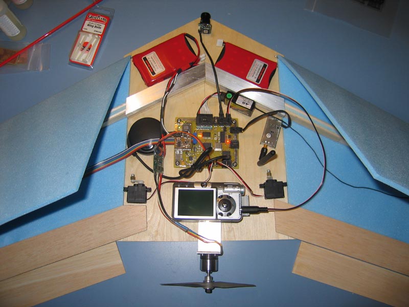
GPS Guided Autonomous Photography Airplane


            Our GPS Guided Autonomous Photography Airplane project is an Unmanned Aerial Vehicle (UAV) that we are very interested in completing successfully.  We have a strong personal interest in remote controlled aircraft, and in Advanced Digital Signals Laboratory last semester we built a flying wing and control systems to fly it from a laptop computer with a wireless video camera mounted on the front of the airplane.  Now we want to take this airplane to the next level, being fully autonomous.  We feel this is an ambitious project that will push us to advance our skills in controls, signal processing, and artificial intelligence.

            Our main goal is to develop a UAV that once launched will autonomously climb in altitude, fly to the preprogrammed coordinates, take photos of the area, and then return safely to the takeoff location.  This would be useful for the government in aerial reconnaissance or search and rescue; or commercially for mapping, artistic photography, or land marketing.  It would also provide a low cost alternative to hiring a manned airplane and would not require any extensive knowledge to use.

Benefits
  • Low cost.
  • Ease of use.
  • Safer than sending a real pilot (zero human expense in military terms).
  • Faster than manned aircraft.
 Features
  • Onboard digital camera for aerial still images.
  • Onboard camera and 2.4GHz transmitter for real time video.
  • Onboard control system capable of switching from manual control to completely autonomous flight at the flip of a switch.
  • Fast deployment – can be ready to launch within seconds.


Wireless Roaming Web Cam


The purpose of this report is to describe, in detail, our implementation of a Wireless web
Cam project. Our project involves moving a robot, which transmits 128 x 128 pixel
images to a PC, via a Graphical user Interface (GUI). Communication between the robot
and the PC in this project is achieved using two RF links, one dedicated to the
transmission of movement commands to the robot and the other dedicated to the image
transmission. It should be noted that it was originally intended to transmit images and
control our robot through a web interface. However, even though this report will mention
about the web interface, due to difficulties experienced in synchronizing and displaying
an image, it was decided that a GUI be used instead.

Our approach to this project was to decompose our solution into several subsystems,
each of which addresses a particular design area and its functionality. The three sections
to follow discuss the various subsystems in detail. We include in each of the sections the
design implementation, as well as reasons for our design choices. The first section
discusses the mechanical design and motor subsystem. The second section explains the
camera and RF subsystem. The third main section of this report outlines the GUI, web
interface and image processing software design.
FOR MORE ANY DETAILS COMMENT HERE WE WILL PROVIDE YOU ALL THE DETAILS

Model Lighthouse Project

Model Lighthouse Project
This project was designed for a model lighthouse
to flash a lamp in a simple sequence: two flashes
of 2s with a short gap of 1s, followed by a longer
gap of 5s before repeating the sequence.
LED on
LED off
2s 1s 2s 5s sequence
repeats
output high: Q0 Q1 Q2 Q3 Q4 Q5 Q6 Q7 Q8 Q9 Q0

The 555 timer is connected as an astable to provide clock pulses for the 4017 counter. The 4017 has ten
outputs (Q0 to Q9) and each one becomes high (‘on’) in turn as the clock pulses are received. Outputs Q0,
Q1, Q3 and Q4 are combined with diodes to produce the flash sequence. A transistor amplifies the current
to power the lamp, or LED if you prefer (a 470W LED resistor is included on the stripboard layout). The
1MW preset controls the time period (T) of the 555 astable from about 0.1 to 1.5s, for example set T = 1s.
For a different flash sequence connect the diodes to combine different 4017 outputs (Q0-Q9). If the full
count from 0 to 9 is not required one of outputs can be connected to the reset input (pin 15). For example
connecting Q8 (pin 9) to reset (pin 15) reduces the long gap at the end of the sequence to 3s (with T=1s).

Cell Phone Controlled House Automation


Cell Phone Controlled House Automation

I.       Introduction
           
            A cell phone is quickly becoming one of the items we never leave home without. Using a cell phone, we wish to be able to control and acquire the status of several devices that exist in one’s home. In particular, we want to be able adjust the temperature using commands sent by a cell phone, and also be able to receive the home temperature status. We would also want to control a security camera remotely for home security purposes.

            Benefits:
·         Users can receive status of devices in the home while away
·         Heating and cooling can be controlled remotely
·         Surveillance camera can be switched remotely
           
            Features:
·         Ability to use cell phone or an internet connected computer to send commands
·         Commands sent through SMS, so nearly any cell phone can be used to send commands
·         Bluetooth communication with lights and thermostat, so no extra wiring is needed
·         No special software needs to be installed on either the cell phone or computer that sends commands

Performance Requirements

  • Indoor transmitter range of at least 70 ft
Response time from sending messages to device response kept below 2 minutes

Cost Analysis
Labor:
      ($65/hour)(150 hours)(2 people)(2.5) = $48750 
Part
Cost
Quantity
Total
Bluetooth HCl Adapter
$69.00
3
$207.00
Camcorder
$350.00
1
$350.00
Antenna with SMA connector
$18.00
2
$36.00
Basic Stamp 2px
$80.00
1
$80.00
Radio aircraft transmitter & reciever
$400.00
1
$400.00
Solid State Relay
$3.00
2
$6.00
Cell Phone Charger
$5.00
2
$10.00
microcontrollers
$5.00
3
$15.00
passive components (capacitors, resistors, diodes, etc.)
$0.03
100
$3.00
other (unknown) circuit components
$30.00
1
$30.00
circuit boards
$4.00
2
$8.00
 LCD Panel
 $20
 1
$20.00
 Temperature sensor
 $7

$7.00


$0.00


$0.00
Total:


$1,1172.00